| Infrared Nano-Optics of Quantum Materials | |||
|---|---|---|---|
Near-Field Infrared Imaging at Cryogenic Temperatures
The characterizations of rich optical phenomena in materials under conditions of extreme temperature and pressure has conventionally relied on far-field spectroscopy techniques. In contrast, the fundamental features of many phase transitions can only be revealed at characteristically nanometer length scales, where the diffraction limit prohibits investigation by far-field spectroscopy instruments, proving the need for tools capable of nanoscale optical characterization of transitions in systems such as superconductors, correlated oxides, and Bose-Einstein condensates of surface polaritons. Nanoscale infrared investigations of these interesting systems have yet to be performed at their transition temperatures. For this reason, our lab has developed a cryogenic scanning near-field optical microscope (Cryo-SNOM) capable of infrared imaging at temperatures down to 40K and pressures of 1e-8 mbar. Current samples of interest for characterization with this instrument include the low-temperature transition oxides V2O3 and Fe3O4, magnetically doped semiconductors like GaMnAs, as well as single-layer graphene subjected to ultra-high vacuum conditions.
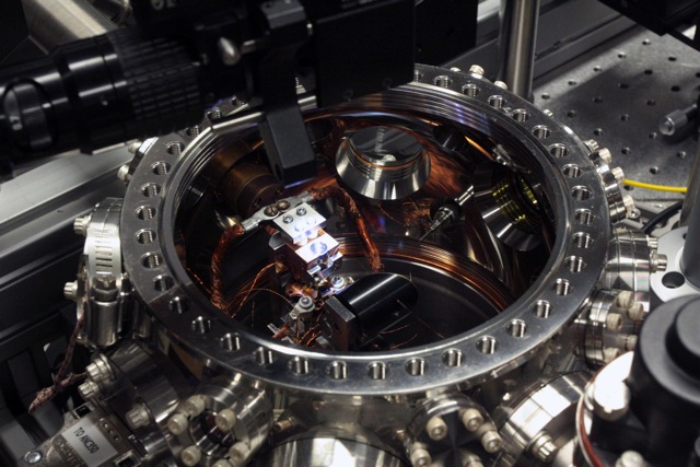
View of the exterior of the Cryo-SNOM chamber: The AFM head is positioned at the lighted area in the center of the chamber, with an optical inspection camera positioned above. Laser illumination enters from a ZnSe window (yellow, left inside the chamber), and focused onto the AFM tip by the parabolic mirror (black, foreground inside chamber).
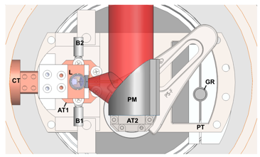
Detailed view of the chamber interior: CT = cryostat (cold finger), L = lens, AT1 = attocube stack 1 (Attocube), B1 = braid connector, B2 = braid connector, PM = parabolic mirror, AT2 = piezo positioning stack 2 (Attocube), PT = platform, GR = glass rod coupling. For cooling the sample, flexible copper braids (not shown in this schematic) are attached from CT to B1 and B2.
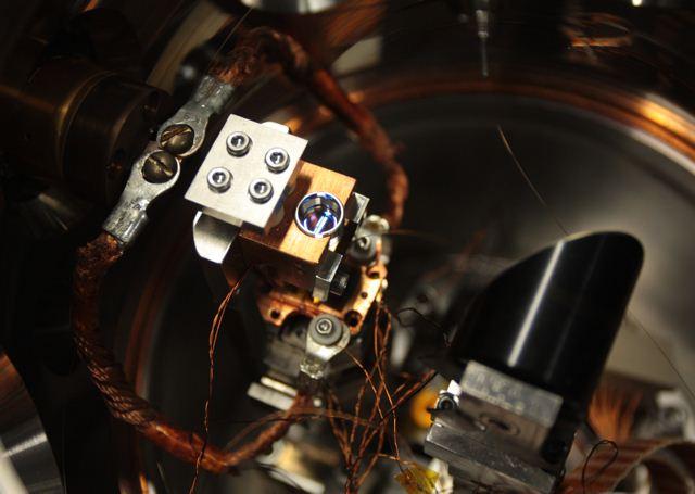
Detail of the AFM head, sample stage, and cooling braids connected to the cold finger of the system cryostat. The optical fiber used for interferometric detection of AFM cantilever deflection is seen entering the chamber through a feedthrough at the top. The parabolic mirror standing in the foreground on a piezo positioning stack focuses laser light onto the AFM tip. |
|||
t |
|||